dchew
Well-known member
And how to adjust minimum ball tension, all while probably killing your warranty in the process.
I really want to like the Arca Swiss P0h. It has almost everything: Light weight, pan top, compact fast movement AND precise gear driven control. Two things I don’t like, one that it doesn’t have and one that it does:
If only I could separate the two parts! I could mount the goniometer part directly onto the RRS leveling base. I would lose the ability to tilt more than 30 degrees (geared range plus leveling base range). But I can’t remember the last time I needed to tip the camera up or down more than 30 degrees. I would still miss the panning base and could add one from RRS, but that kills the real weight advantage of this head. So I will do without a panning base.
Off I went: it turns out it is relatively easy to separate the two halves. Start by turning the big silver ring all the way to loosen the ball. Remove 4 screws holding the bottom aluminum flange (Philips head):
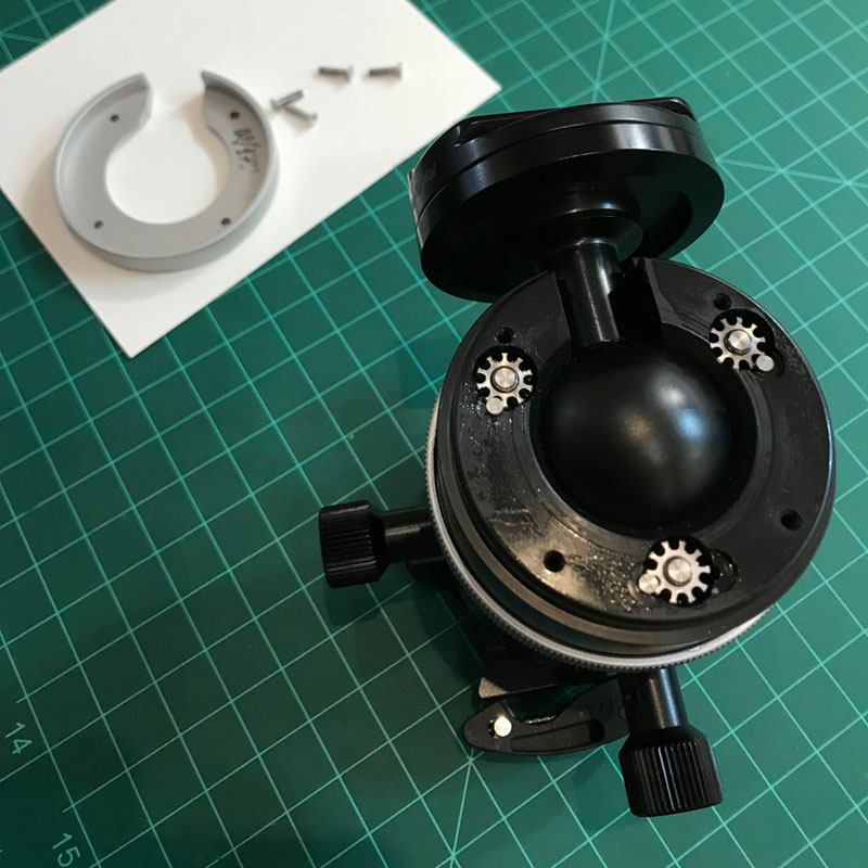
This looks a little intimidating, but those lock pins lift right out:
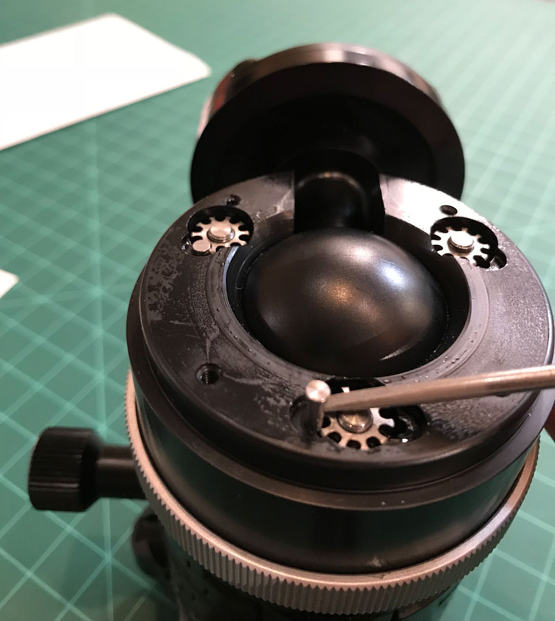
These funny looking nuts are what adjust the tension setting. Here is the main reason for my post: If you want less play in the ball when you fully loosen the ring, you can disassemble the bottom flange to this point. Remove the three lock pins and simply tighten each of the three nuts up a notch or two. They are reverse threads, so that means rotating them counter-clockwise a notch to tighten. Do them evenly to keep clamp pressure even on the ball. Put the pins back in and check it. Rinse and repeat as much as necessary. Just remember to put the pins back in every time before you tighten the big silver ring. If you forget, the nuts can spin as you tighten, and you will then have to readjust them as best you can.
But of course, I wanted to keep going! Once you figure out the funny looking nuts are reverse thread, they just spin right off. Here is a poor close pic with the nut removed:
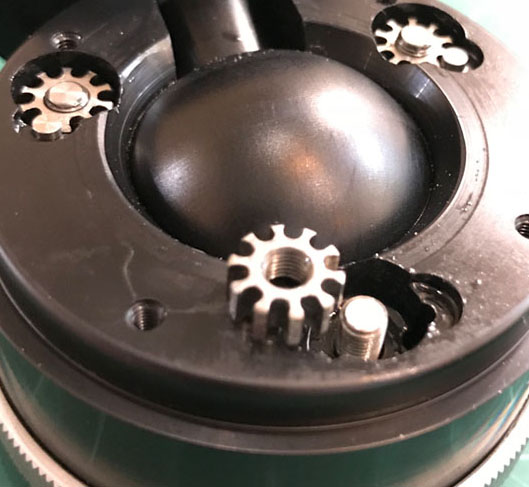
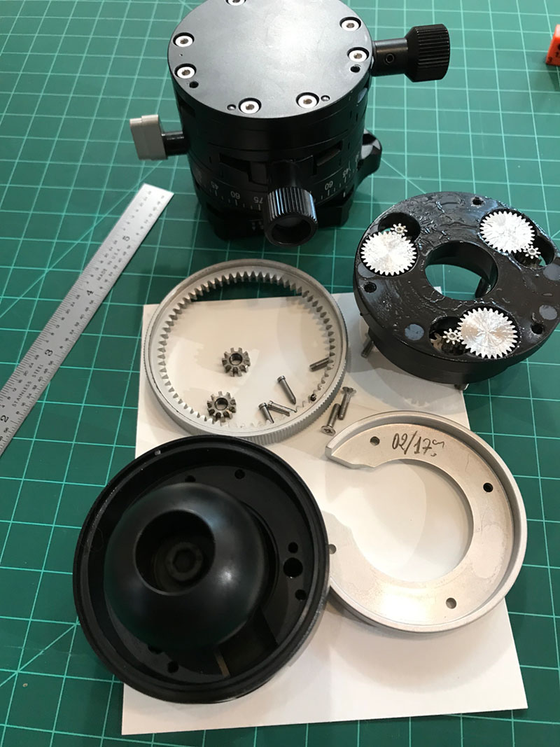
Once you get all three nuts removed, the black plastic piece comes right off, along with the ball. Then you will find three screws buried down in those half-holes. This is the trickiest part of the process. Turns out those screws are #6-40 screws with 5/64 hex head. Be careful not to strip the head because they use white locktite on these screws. Ask me how I know…
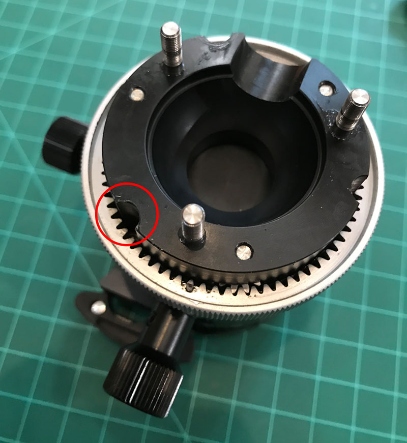
Once those three screws are off, that’s it. Here are all the pieces strewn about. Notice all the protective goop (technical term) on the gear assembly:
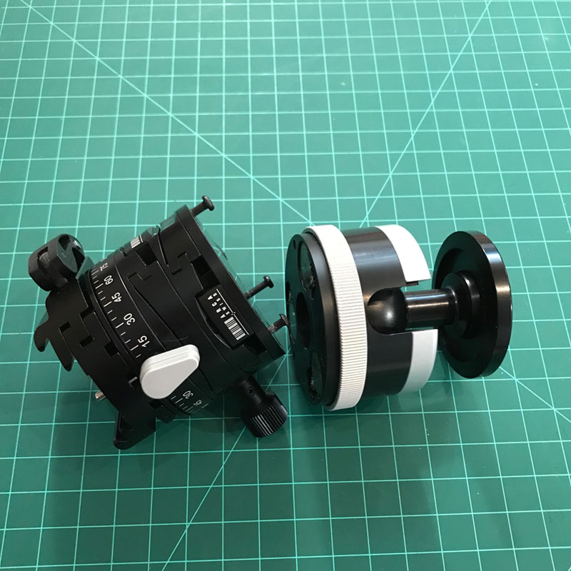
And here are the two halves of my assistant after my "sawing the box in half" magic trick, with the original screws back in their threads:
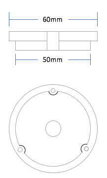
I won't be using the bottom half at all. My plan is to make the part below in delrin or aluminum. Three holes through this piece for the original #6-40 screws, mounted into the base of the goniometer (top half) using the original threads. The center hole will be 3/8-16 to accept the RRS TH-DVTL-40 plate that attaches to the leveling base.
More to come…
I really want to like the Arca Swiss P0h. It has almost everything: Light weight, pan top, compact fast movement AND precise gear driven control. Two things I don’t like, one that it doesn’t have and one that it does:
- I wish it had a panning base on the bottom.
- I wish it didn’t have the ball and associated skinny stem.
If only I could separate the two parts! I could mount the goniometer part directly onto the RRS leveling base. I would lose the ability to tilt more than 30 degrees (geared range plus leveling base range). But I can’t remember the last time I needed to tip the camera up or down more than 30 degrees. I would still miss the panning base and could add one from RRS, but that kills the real weight advantage of this head. So I will do without a panning base.
Off I went: it turns out it is relatively easy to separate the two halves. Start by turning the big silver ring all the way to loosen the ball. Remove 4 screws holding the bottom aluminum flange (Philips head):
This looks a little intimidating, but those lock pins lift right out:
These funny looking nuts are what adjust the tension setting. Here is the main reason for my post: If you want less play in the ball when you fully loosen the ring, you can disassemble the bottom flange to this point. Remove the three lock pins and simply tighten each of the three nuts up a notch or two. They are reverse threads, so that means rotating them counter-clockwise a notch to tighten. Do them evenly to keep clamp pressure even on the ball. Put the pins back in and check it. Rinse and repeat as much as necessary. Just remember to put the pins back in every time before you tighten the big silver ring. If you forget, the nuts can spin as you tighten, and you will then have to readjust them as best you can.
But of course, I wanted to keep going! Once you figure out the funny looking nuts are reverse thread, they just spin right off. Here is a poor close pic with the nut removed:
Once you get all three nuts removed, the black plastic piece comes right off, along with the ball. Then you will find three screws buried down in those half-holes. This is the trickiest part of the process. Turns out those screws are #6-40 screws with 5/64 hex head. Be careful not to strip the head because they use white locktite on these screws. Ask me how I know…
Once those three screws are off, that’s it. Here are all the pieces strewn about. Notice all the protective goop (technical term) on the gear assembly:
And here are the two halves of my assistant after my "sawing the box in half" magic trick, with the original screws back in their threads:
I won't be using the bottom half at all. My plan is to make the part below in delrin or aluminum. Three holes through this piece for the original #6-40 screws, mounted into the base of the goniometer (top half) using the original threads. The center hole will be 3/8-16 to accept the RRS TH-DVTL-40 plate that attaches to the leveling base.
More to come…
Last edited:
")