I discussed the challenge of making perfectly accurate focus using tech cameras with MFDB in previous post (#31).
A quick summary, at least in my case, the best possible method with the presently available technologies to achieve perfect focus is by using 'lens equation' with accurate object distance measurement and a precisely indexed focus ring. A lens equation, for a specific lens with a specific focusing system, can be developed mathematically. The 'lens equation' will provide the required angular rotation of a focus ring for a measured object distance.
First, I would like to 'rant' against all View Camera and Tech Camera manufacturers for their failure to promote (i.e. to educate their customers) properly how to use the features they are building into their camera. It is a shame that they let the customers to rely upon HF (hyper focal) or 'focus stacking' for proper focusing, or '35mm rule of thumb' for lens tilt calculation after spending a small fortune on equipment that boast 'multi mega pixels', '13 f-stop dynamic range' and 'lens with resolving power to see the sub atomic particles', etc. Why can they develop and provide more than a 'satisfactory' solutions to the challenges their customers face? Enough with ranting.
Let't talk about Tilt or Swing in Tech Camera application.
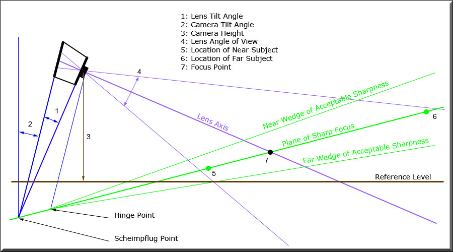
A simple geometric diagram for Tilt (both camera and lens) is shown above.
The Plane of Sharp Focus is defined by two points photographer select to be in 'sharp' focus, Near Subject (or Object) and Far Subject. Camera Height, Camera Tilt angle and a specific lens are also defined by photographer to compose the image properly. The lens Tilt Angle and the required Focus Distance are the results of these five input data (the location of Near and Far Subjects, Camera Height reference to the ground, a lens focal length and Camera Tilt Angle). In addition, Near and Far Wedges of Acceptable Sharpness (Angular DOF) are defined by a user selected CoC.
The real challenge of using Tilt or Swing with View Camera or Tech Camera is not finding a lens Tilt Angle but the required Focus Distance after a tilt is made. Harold Merklinger published two books (The Ins and OUTs of Focus, Focusing the View Camera) on the subject of Lens Tilt in details.
Once I was satisfied with the results of 'Lens Equation' in achieving a perfect focus with a measured Object Distance, I decided to tackle the challenge of Lens Tilt (or Swing). It is rather complex geometric calculations but doable using a spreadsheet, such as Excel or Numbers. It took me much longer than I expected (my mathematical brain atrophied significantly over last 40 years) but I completed the project and have been using since last Spring.

The picture above shows the setup I use for both leveled and lens tilted application. It maintains the exact geometric configuration between Rm3di and Disto 5 so I can always accurately measure the Object Distance or Near (Far) Object locations. Since all Disto measurement are offset from Lens Axis, Lens Nodal Point and DB sensor plane, proper corrections are made in the program.
Near (and Far) Object locations should be measured by their horizontal and vertical distance from the lens nodal point. Disto 5 has a function to measure them (Direct Horizontal Distance).
I made a quick shot this morning after reading "Torger's" comment. I used SK90, placed two $20 bills on the floor (1.96m and 3.22m away from the camera, and the nose of Andrew Jackson was the targets), camera was tilted 23.8 degree and the camera height was 0.96m. The required lens tilt was 4.82 degree and the calculated focal distance was 2.14m, therefore the index setting of Red 22.1. The aperture setting was 8.0.
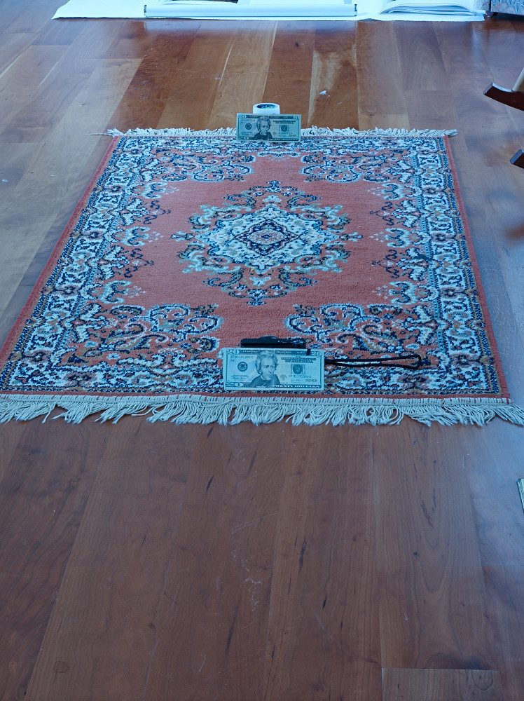
Images are directly from C1 without any enhancement.
 100% of Front US$20 bill.
 100% of Back US$20 bill.
One additional picture I took while working on the program, Lens Swing. I superimposed 100% images of two blocks, front and back.

This is the one man's story to use a tech camera, Rm3di, for its full potential.
There are several mechanical designs of Rm3di which I wish they improve soon.
1. There are no indentations (mechanical click) for both vertical and horizontal shift center positions.
2. Thumb dial for Lens Tilt needs major improvement, for both accuracy of setting and ease of use.
3. Helical ring is too tight to rotate. I understand its need to stay at a set point but the friction could be much less.
4. Focus setting point should be a 'fine line' much closer to the index markers.
Jae Moon
A quick summary, at least in my case, the best possible method with the presently available technologies to achieve perfect focus is by using 'lens equation' with accurate object distance measurement and a precisely indexed focus ring. A lens equation, for a specific lens with a specific focusing system, can be developed mathematically. The 'lens equation' will provide the required angular rotation of a focus ring for a measured object distance.
First, I would like to 'rant' against all View Camera and Tech Camera manufacturers for their failure to promote (i.e. to educate their customers) properly how to use the features they are building into their camera. It is a shame that they let the customers to rely upon HF (hyper focal) or 'focus stacking' for proper focusing, or '35mm rule of thumb' for lens tilt calculation after spending a small fortune on equipment that boast 'multi mega pixels', '13 f-stop dynamic range' and 'lens with resolving power to see the sub atomic particles', etc. Why can they develop and provide more than a 'satisfactory' solutions to the challenges their customers face? Enough with ranting.
Let't talk about Tilt or Swing in Tech Camera application.
A simple geometric diagram for Tilt (both camera and lens) is shown above.
The Plane of Sharp Focus is defined by two points photographer select to be in 'sharp' focus, Near Subject (or Object) and Far Subject. Camera Height, Camera Tilt angle and a specific lens are also defined by photographer to compose the image properly. The lens Tilt Angle and the required Focus Distance are the results of these five input data (the location of Near and Far Subjects, Camera Height reference to the ground, a lens focal length and Camera Tilt Angle). In addition, Near and Far Wedges of Acceptable Sharpness (Angular DOF) are defined by a user selected CoC.
The real challenge of using Tilt or Swing with View Camera or Tech Camera is not finding a lens Tilt Angle but the required Focus Distance after a tilt is made. Harold Merklinger published two books (The Ins and OUTs of Focus, Focusing the View Camera) on the subject of Lens Tilt in details.
Once I was satisfied with the results of 'Lens Equation' in achieving a perfect focus with a measured Object Distance, I decided to tackle the challenge of Lens Tilt (or Swing). It is rather complex geometric calculations but doable using a spreadsheet, such as Excel or Numbers. It took me much longer than I expected (my mathematical brain atrophied significantly over last 40 years) but I completed the project and have been using since last Spring.
The picture above shows the setup I use for both leveled and lens tilted application. It maintains the exact geometric configuration between Rm3di and Disto 5 so I can always accurately measure the Object Distance or Near (Far) Object locations. Since all Disto measurement are offset from Lens Axis, Lens Nodal Point and DB sensor plane, proper corrections are made in the program.
Near (and Far) Object locations should be measured by their horizontal and vertical distance from the lens nodal point. Disto 5 has a function to measure them (Direct Horizontal Distance).
I made a quick shot this morning after reading "Torger's" comment. I used SK90, placed two $20 bills on the floor (1.96m and 3.22m away from the camera, and the nose of Andrew Jackson was the targets), camera was tilted 23.8 degree and the camera height was 0.96m. The required lens tilt was 4.82 degree and the calculated focal distance was 2.14m, therefore the index setting of Red 22.1. The aperture setting was 8.0.
Images are directly from C1 without any enhancement.
One additional picture I took while working on the program, Lens Swing. I superimposed 100% images of two blocks, front and back.
This is the one man's story to use a tech camera, Rm3di, for its full potential.
There are several mechanical designs of Rm3di which I wish they improve soon.
1. There are no indentations (mechanical click) for both vertical and horizontal shift center positions.
2. Thumb dial for Lens Tilt needs major improvement, for both accuracy of setting and ease of use.
3. Helical ring is too tight to rotate. I understand its need to stay at a set point but the friction could be much less.
4. Focus setting point should be a 'fine line' much closer to the index markers.
Jae Moon
Last edited:
")